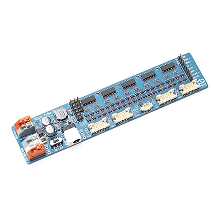
Step 1: Include the Omnixie_NTDB.h library
#include <Omnixie_NTDB.h>
Step 2: define how many NTDB boards in use
#define NTDB_count 1
Step 3:
Omnixie_NTDB nixieClock(11, 8, 12, 10, 6, 5, NTDB_count);
// pin_DataIN, pin_STCP(latch), pin_SHCP(clock), pin_Blank(Output Enable; PWM pin preferred),
// HVEnable pin, Colon pin, number of Nixie Tube Driver Boards
// PWM Pins on Arduino Uno: 3, 5, 6, 9, 10, 11; PWM FREQUENCY 490 Hz (pins 5 and 6: 980 Hz)
Step 4:
//turn on the high voltage provided by NCH6300HV
  nixieClock.setHVPower(true);

  // Brightness control, range 0x00(off) to 0xff(brightest).
  nixieClock.setBrightness(0xff);
  //turn on the tube display
  nixieClock.display();
Step 5:

for (int n = 0; n < 9999; n++) {
    //Specify what number to display, and which tubes to display
    nixieClock.setNumber(n, 0b1111);
    //Light up the tubes
    nixieClock.display();
    delay(10);
}
Here is the complete project.
/*
  Nixie Tube Driver Board (NTDB) 4-Nixie Tube Display Minimal Example

  This example demonstrates a minimal display using 4 nixie tubes.
  No colon bulbs. No buttons/controls. No clock.
  See aother example we provided for a complete clock.

  In order to make a complete clock, you will need:
  1) This KIT: https://nixie.ai/ntdb4
  2) 4x nixie tubes
  3) 1x NCH6300HV: https://nixie.ai/nch6300hv
  4) 1x Arduino Uno board
  5) 1x Real Time Clock module (DS1307, DS3231, etc)
  6) Some jumper wires


  Circuit:
  Connect the NTDB to Arduino Uno:
  --------------------------------
    NTDB        Arduino Pins
  --------------------------------
    GND         GND
    DC5V
    DATA        11
    OE          10
    STCP        8
    SHCP        12
    COLON       5 (Not In Use)
    ON/OFF      6 (HVEnable)
  --------------------------------
  Connect the 12V DC power to the NTDB board


  Nixie Tube Driver Board (NTDB) Arduino Library released at
  https://github.com/omnixie-electronics/Nixie-Tube-Driver-Board-Arduino-Library
  with short link: https://nixie.ai/ntdb4github

  First released in public domain on Thanksgiving day, 11/26/2020
  Library and example code created
  by Aiden Fang
  www.Omnixie.com

  NTDB board designed by Zeyuan, Yan
  www.Omnixie.cn

*/

#include <Omnixie_NTDB.h>


#define NTDB_count  1
// define how many NTDB boards in use

Omnixie_NTDB nixieClock(11, 8, 12, 10, 6, 5, NTDB_count);
// pin_DataIN, pin_STCP(latch), pin_SHCP(clock), pin_Blank(Output Enable; PWM pin preferred),
// HVEnable pin, Colon pin, number of Nixie Tube Driver Boards
// PWM Pins on Arduino Uno: 3, 5, 6, 9, 10, 11; PWM FREQUENCY 490 Hz (pins 5 and 6: 980 Hz)

void setup()
{
  //turn on the high voltage provided by NCH6300HV
  nixieClock.setHVPower(true);

  // Brightness control, range 0x00(off) to 0xff(brightest).
  nixieClock.setBrightness(0xff);
  //turn on the tube display
  nixieClock.display();

  //quickly loop through all digits to prevent cathode poisoning
  CathodePoisoningPrevention(3, 100);

}

void loop()
{
  for (int n = 0; n < 9999; n++) {
    //Specify what number to display, and which tubes to display
    nixieClock.setNumber(n, 0b1111);
    //Light up the tubes
    nixieClock.display();
    delay(10);
  }
}

void CathodePoisoningPrevention(unsigned int num, int msDelay) {
  if (num < 1) exit;
  for (byte n = 0; n < num; n++) {
    Serial.println("Running Cathode Poisoning Prevention ... ");
    for (byte i = 0; i < 10; i++) {
      nixieClock.setNumber(i * 1111, 0b1111);
      nixieClock.display();
      delay(msDelay);
    }
  }
  delay(1000);
}